
Summary
In highspeed Surface Mount Technology (SMT) assembly, reel changeovers are one of the most frequent sources of hidden loss—driving downtime, startup waste, feeder wear, and vision alarms. SMT splice tape enables inline splicing, allowing operators to join the end of a running reel to the start of a new reel with minimal interruption.
This guide explains what SMT splice tape is, what “highquality” means in production terms, and how to select splicing solutions that support stable feeder passthrough and reliable optical recognition.
What Is SMT Splice Tape?
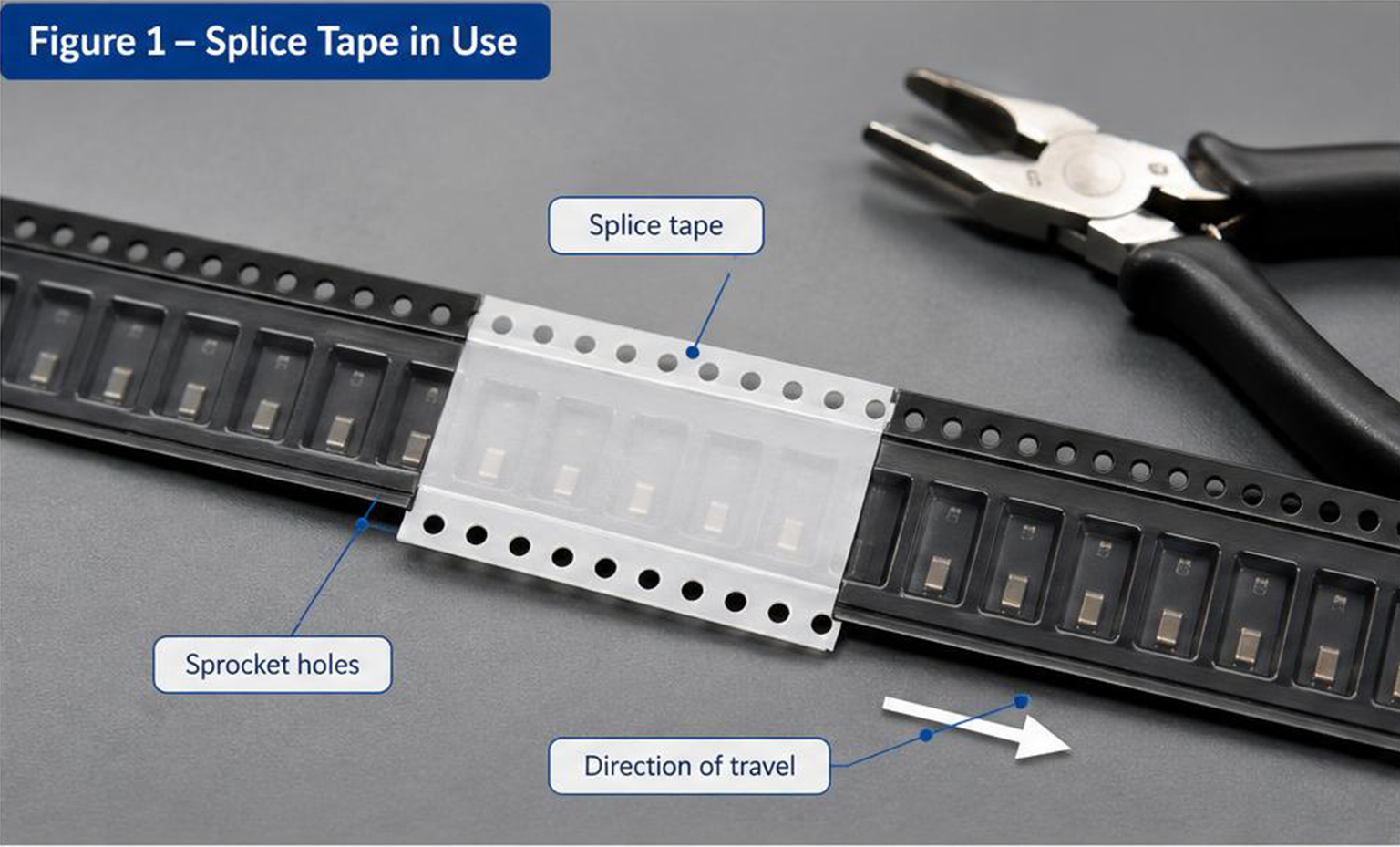
SMT splice tape is a highadhesion technical tape designed to join:
the tail of a depleted component carrier tapeto
the head of a new reel’s carrier tape
This joining process—often called splicing—allows the pickandplace system to keep feeding components without stopping to fully rethread or recalibrate the feeder for each reel.
In practice, splice tape is used with a standard workflow:
prepare the new reel,
align the carrier tapes and sprocket holes,
apply splice tape (and shims/clips if needed),
verify stable passthrough and vision recognition.
The Anatomy of a HighQuality Splice (What Actually Matters on the Line)
Not all splice tapes perform the same. “Good” splice tape is defined by predictable behavior in the feeder and the splice zone.
1) Adhesion That Bonds Fast—and Stays Stable
The adhesive must bond reliably to common carrier tape materials (plastic or paper) while maintaining stability under line conditions.
What to evaluate
Bond consistency across batches
Resistance to lifting at edges during indexing
Residue risk (especially on feeders and guides)
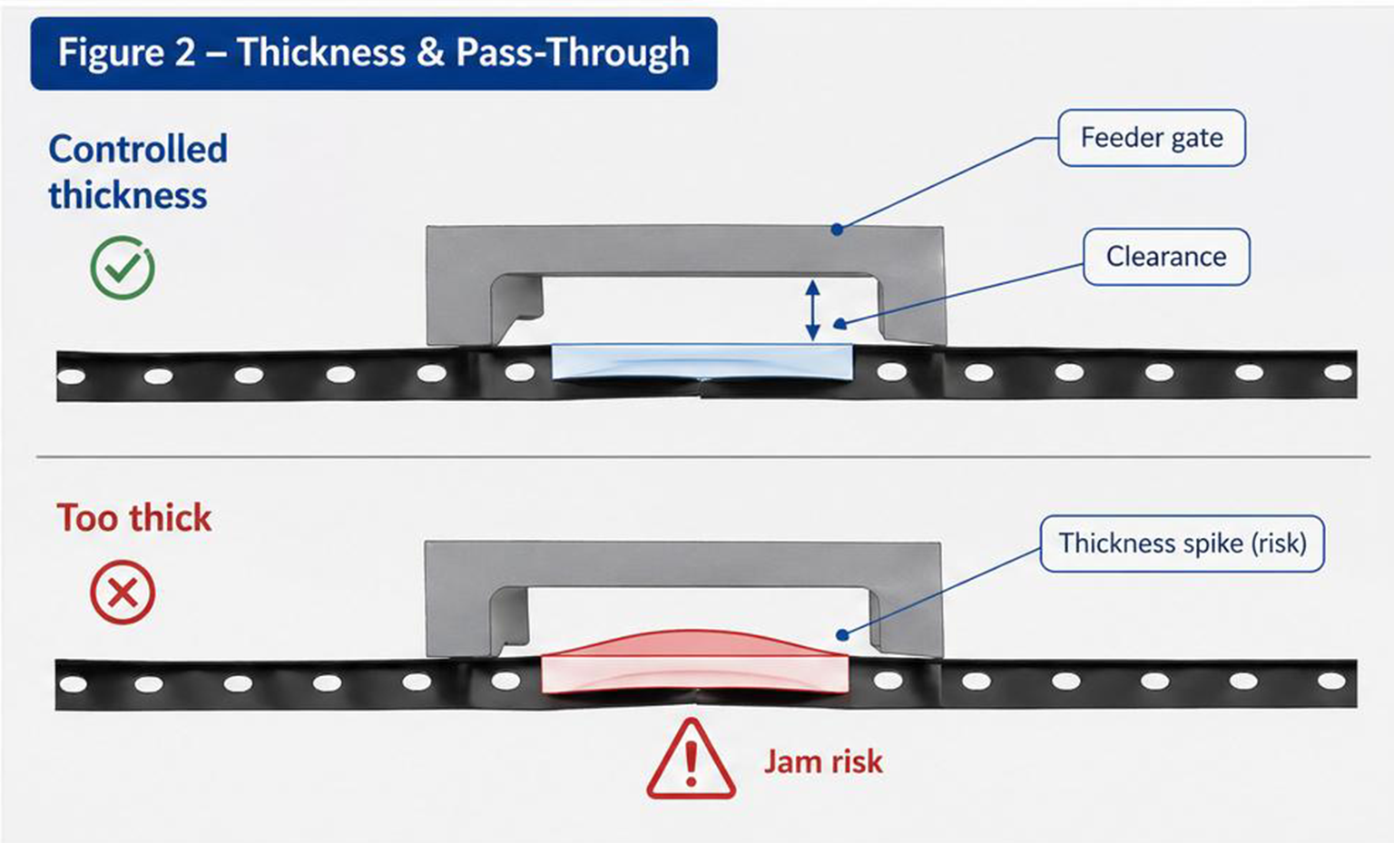
2) Controlled Thickness for Feeder PassThrough
Highspeed feeders operate on tight mechanical tolerances. If the splice is too thick, uneven, or curled, it can cause:
gate interference
jams
sensor/position errors
What to evaluate
Splice thickness profile and flatness
Smooth passage through the feeder gate and guides
3) Sprocket Hole Registration and Alignment
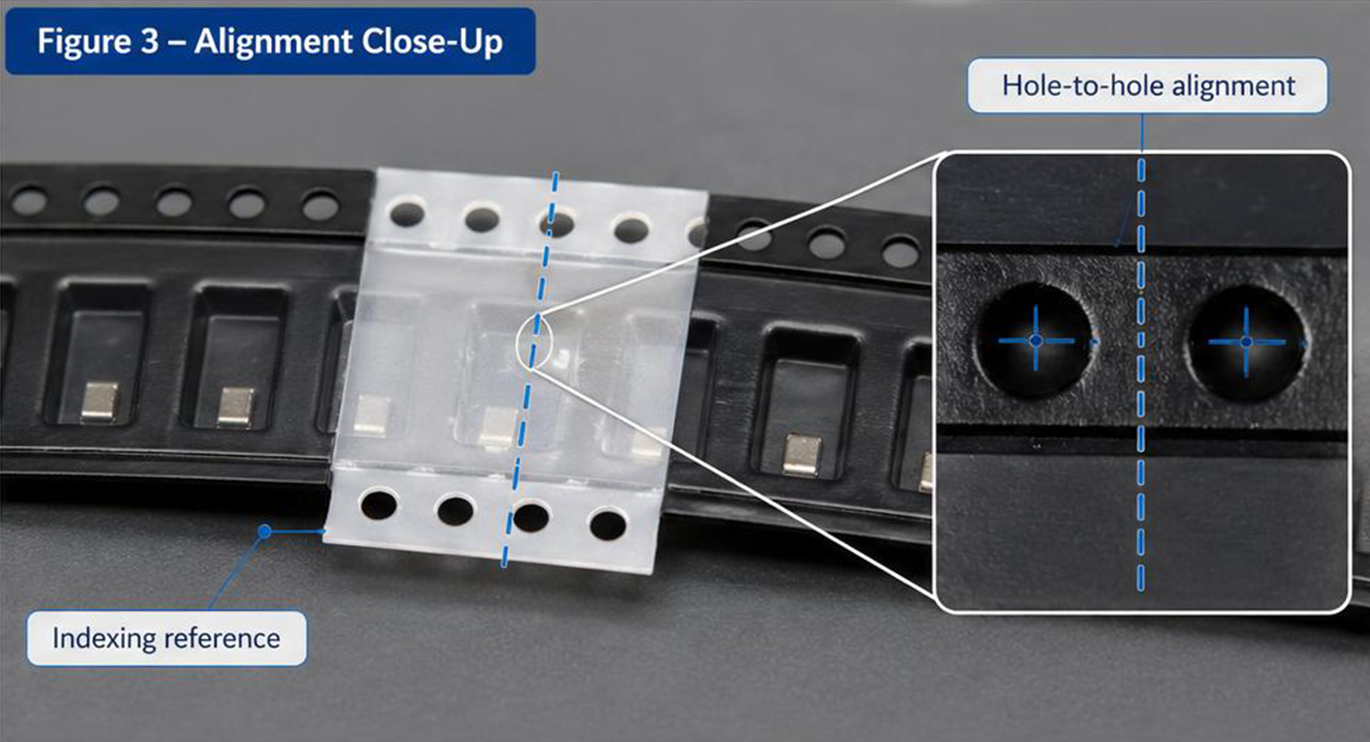
Modern feeders and vision systems depend on accurate sprockethole geometry. Small alignment errors can trigger:
vacuum errors
mispicks
alignment alarms
What to evaluate
holetohole alignment through the joint
consistent indexing rhythm across the splice zone
Why SMT Splice Tape Matters (Business Impact)
For a modern SMT line, stopping a machine to change reels is expensive. Splicing reduces frequent stopandgo behavior and improves repeatability during highmix production.
1) Maximize Uptime and Improve OEE
Traditional reel changes can require stopping the machine, unthreading feeders, and rethreading new reels. When repeated across multiple feeders, small stoppages compound into meaningful OEE loss.
Splicing supports continuous feeding, reducing interruption frequency and helping lines maintain stable throughput.
2) Reduce Startup Waste
Manual threading often consumes a leader section and can discard early components during “seek/alignment” phases. A stable splice can help teams recover more usable components—especially important for highvalue ICs and constrained supply.
3) Protect HighSpeed Feeders and Reduce Maintenance Burden
Improvised tapes and inconsistent joints can leave residue, attract debris, or create thickness spikes that increase mechanical wear. Controlled, productiongrade splicing reduces longterm risk to highcapital feeder systems.
4) Improve Optical Recognition Near the Splice Zone
A wellaligned joint keeps the carrier tape flat and sprocket holes registered, reducing the chance of visionsystem variability and mispick errors.
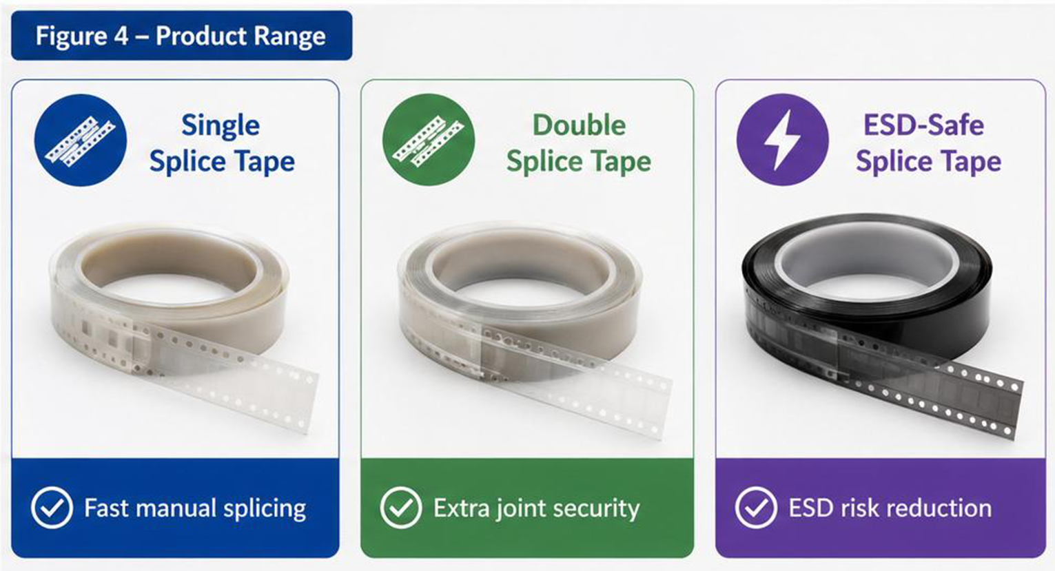
Single vs Double Splice Tape (When to Use Which)
Figure 2 — Splice Tape Types at a Glance
Selection depends on your feeder type, carrier tape material, and the mechanical stress around the splice zone.
ESDSafe Splice Tape (When It Matters)
During highspeed tape peeling and handling, static charge can accumulate. For ESDsensitive devices, incorporate splice tape choice into your broader ESD control program (work surfaces, wrist straps, ionization, packaging, auditing).
Use ESDsafe splice tape when:
you handle ESDsensitive semiconductors, sensors, or modules
your factory follows an ESD control program and wants lower process risk
Practical Setup Checklist (Repeatability > Heroics)
Standardize your splicing method so results don’t depend on who is on shift:
Match tape width/pitch to the feeder and carrier tape
Keep the joint area clean (dust/oil increases failure risk)
Align sprocket holes before bonding
Apply even pressure across the joint for flatness
Verify passthrough at low speed before full production speed
Use shims/clips and splice tools for critical lines or tight tolerances