
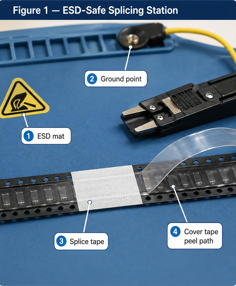
Summary
Reel changeovers and tape peeling can generate static electricity—especially in dry environments and highspeed handling. For ESDsensitive components, an uncontrolled ESD event may cause latent damage that is difficult to detect at final test.
This guide explains where static comes from during SMT splicing, how ESDsafe splice tape fits into an ESD control program, and what to standardize on the line to reduce risk.
Why Reel Changeovers Are an ESD Risk Zone
Static charge can build up when:
cover tape peels at high speed (triboelectric effect)
carrier tape slides through guides and gears
operators handle reels, trays, and tape segments without consistent grounding
humidity is low and ionization is insufficient
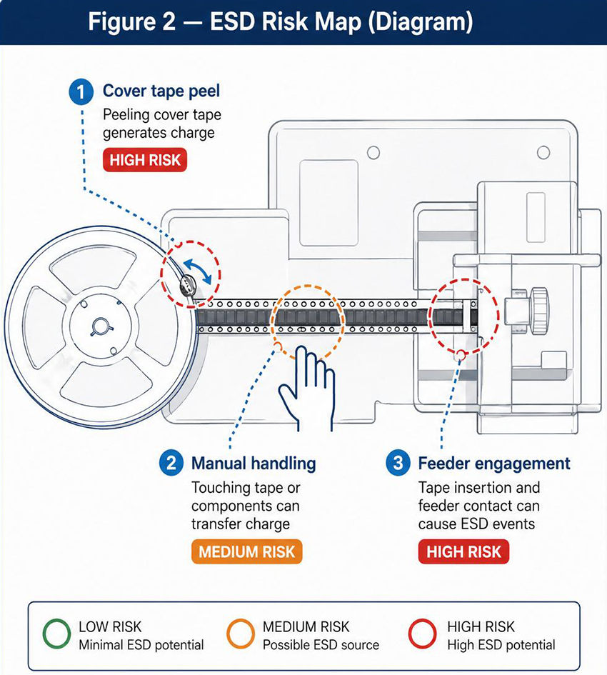
Even if the line runs smoothly, ESD risk can increase around:
manual splicing points
feeder loading/unloading
tape peel-off areas near the pick window
What “ESDSafe Splice Tape” Means (and What It Doesn’t)
ESDsafe splice tape is designed to help reduce static accumulation/charge retention during the splicing and feeding process. In practice, it is a riskreduction component—not a replacement for a complete ESD control program.
ESDsafe splice tape can help
reduce static charge retention on the tape surface (material dependent)
support consistent handling where ESD controls are already implemented
ESDsafe splice tape does not replace
ESD flooring, wrist straps, grounding points
ionizers (where required)
packaging controls and auditing
ESD training and workstation discipline
Where ESD Damage Happens in the Splicing Workflow
The highestrisk moments are typically:
Cover tape peel and disposal (rapid peel, friction, charge separation)
Manual alignment and pressing (hands + tape + substrate interactions)
Feeder engagement (gear friction, fast indexing)
Best Practices: A Practical ESDSafe Splicing Standard
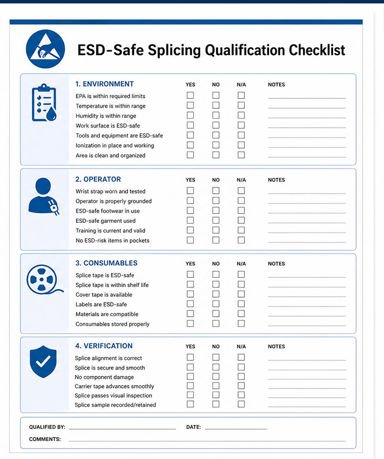
Adopt a standard method so results do not depend on operator habits:
1) Control the Work Surface
Use an ESD mat with a verified ground point
Keep the splicing area clean and dry (dust/oil increases variability)
Place a dedicated disposal for peel-off tape near the station
2) Control the Operator Interface
Require wrist strap usage (and regular strap testing)
Keep finger contact minimal on component tape and exposed areas
Use tools (pliers/jigs) to reduce direct handling
3) Control the Consumables
Use ESDsafe splice tape for ESDsensitive lines
Avoid office tapes or unknown adhesives (residue + uncontrolled static properties)
Match tape thickness to feeder tolerances to avoid jams and rework
4) Verify Process Discipline
Define pass/fail checks: alignment, flatness, residue, feeder pass-through
Audit periodically (different shifts, different operators)
How to Choose the Right ESDSafe Splicing Consumables
When qualifying splice tape, confirm:
carrier tape material (paper/plastic) and compatibility
tape width/pitch range used on your line
feeder type and speed (tight tolerances need controlled thickness)
whether ESD-safe option is required by your program
Common Questions
Q1: Do I need ESDsafe splice tape for every line?
Use it where you handle ESDsensitive devices or where your ESD program requires material controls. For nonsensitive components, standard splice tape may be sufficient.
Q2: If we use ESDsafe tape, do we still need ionizers?
Yes—ionizers address static in the environment and on surfaces. ESDsafe tape is a complementary control, not a replacement.
Q3: What are the warning signs of ESD issues in production?
ESD damage is often latent. Indirect indicators include increased early-life failures, inconsistent test results, and unexplained yield drift—especially correlated with dry conditions or changeover-heavy builds.
Request Samples or a Bulk Quote
To receive recommendations and a quote, share:
component sensitivity (if known) and ESD program requirements
carrier tape width/pitch and feeder model
line speed and changeover frequency
monthly usage estimate and shipping country